Sunday, March 29, 2009

Light Sensor Circuit 1

Tiny Light Sensor With Logic Output Draws Less
Than 10µA

A light-sensing circuit that consumes very little power can
serve as an automatic backlight sensor in portable instruments.
This function is easily implemented with a logic gate or
Schmitt-trigger inverter, but those approaches draw a
considerable amount of supply current.


Figure 1. This light sensor provides a low-to-high output
transition at a light level determined by the value of R1.
more


Sensing Light with a Programmable Gain Amplifier
INTRODUCTION
Photo sensors bridge the gap between light and electronics.
Microchip’s Programmable Gain Amplifiers
(PGAs) are not well suited for precision applications
(such as CT scanners), but they can be effectively used
in position photo sensing applications minus the headaches
of amplifier stability.


Photo sensors can be connected directly to Microchip’s PGA.
Based on the level ofluminance to the photo sensor, the gain
of the signal can be changed through the SPI™ port of the
MCP6S26, six-channel PGA.
more pdf


8 Photo-Detector Circuitboards 
Visible and Infrared Light
A new version of the 8 Photo-Detector circuitboard where the
Outputs Are LOW When The Inputs Are LOW.
(The LEDs are ON when the Phototransistors are exposed to light.)


more


MAKING A LIGHT / DARK SENSOR
Opposite is a simple light/ dark sensor. This can be connected
as an input or switch to another circuit. The sensors has three
green wires (1, 2 and 3). Wire 2 should always be connected
to one of the inputs. If wire 1 is also connected then the sensor
acts as a dark sensor. If wires 2 and 3 are connected to the
inputs then sensor operates as a light sensor.


Photodiode and Light Sensor 


Saturday, March 28, 2009

Ultrasonic Sensor Circuit4

40kHz Ultrasonic Driver Circuit for a few pounds

Here is a circuit diagram for an ultrasonic driver circuit suitable
for the the Speed of ultrasound and Lloyd's Mirror using
Ultrasonic Waves experiments. Test the circuit on a plug-in
prototype board to make sure I've transcribed the component
values correctly. I got the circuit to work on a plug-in prototype
board before it was transferred to a printed circuit board (PCB).
The circuit should work with strip board so you shouldn't need
to make a PCB. If somebody does do PCB artwork (or a strip
board layout) they should publish it on the www and I'll link to it.
Many basic electronics books explain the operation of the 555
chip (the 556 chip is a package of two 555 circuits in a single chip).


Ultrasonic Reflectance Detector
This circuit detects motion within approximately 5 inches of
a piezo-ceramic element ultrasonic transducer. The detection
distance is much smaller than obtainable with other ultrasonic
techniques, however, it only requires a single transducer, as
opposed to the two-transducer arrangement typically found in
other designs. The short-range detection is adequate for many
applications, such as proximity-operated commodity dispensers
or tamper alarms for merchandise cases.


Ultrasonic Range Sensor
1 is the connection to the RCX. D1 - D4 form a bridge rectifier
to obtain local power from the RCX which is stored on C7 and
regulated to 5V by U1, a low power, low dropout regulator.
The microcontroller, U3 is programmed to generate a burst of
8 x 40KHz pulses on pin 6. Q1 switches current into L1 creating
a "flyback" voltage output to Y2, the ultrasonic transmitter, of
about 20V peak. The 40KHz is based on a software division of
the 10MHz reference (the ceramic resonator, Y1, in this case).
Y3, the ultrasonic receiver, is band-limited by L2, to stop normal
sound and vehicle vibration from being the dominant input. L2
is chosen to form a resonant circuit with the self capacitance of
the receiver piezo. It should be peaked for 40KHz. U2D and
U2A are the primary gain stages to get the millivolt level signals
up to a couple of volts.


Ultrasonic Sensor Circuit 3

Arduino + Ultrasonic sensor + MP3

In this project for
Martí Guixé we built a small autonomous device
with
Arduino that can detect the presence of people with an
ultrasonic sensor. It then proceeds to play an MP3 song with a
Yampp Industrial II


Ultrasonic range finder uses few components


Measuring distance with ultrasonic signals requires a transmitting
ultrasonic transducer; a medium, such as air or water; a reflecting
surface or object; a receiving ultrasonic transducer; and a
time-of-flight measurement circuit. The speed of sound in air at
20 C is approximately 343m/sec, which translates to about 1 in. Per
74 Wsec. Doubling the time gives you the round-trip speed, which
is 1 in. per 148 Wsec. Four aspects of the system limit the
maximum measurable distance: the amplitude of the sound wave,
the texture of the reflecting surface, the angle of the surface with
respect to the incident sound wave, and the sensitivity of the
receiving transducer. The receiving transducer's direct reception
of the sonar pulse—and not the echo—usually dictates the
minimum measurable distance.


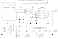
Circuit drawingfor Ultrasonic Range Meter


Friday, March 13, 2009

Ultrasonic Sensor Circuit 2

Ultra-Sonic Ranging Design
This project started after I looked at the Polaroid Ultrasonic
Ranging module. It has a number of disadvantages for use in
small robots etc.
-The maximum range of 10.7 metre is far more than is normally
required, and as a result
-The current consumption, at 2.5 Amps during the sonic burst is truly horrendous.
-The 150mA quiescent current is also far too high.
-The minimum range of 26cm is useless. 1-2cm is more like it.
- The module is quite large to fit into small systems, and
- It’s EXPENSIVE.
Here in the UK from Maplin Electronics, the module costs GB38.00
and the transducer costs a further GB17.00. In fairness, the Polaroid
module does the job it was intended to do, which requires the range,
but that job is not to provide the eyes of a small robot.


more


Ultrasonic switch
Description.
A different type of remote control circuit employing ultrasonic signals
is given here.
The transmitter part of the circuit is build around IC1(NE 555).
The IC1 is wired as an astable multi vibrator operating at 40KHz.
The output of IC1 is amplifier the complementary pair of transistors
( Q1 & Q2) and transmitted by the ultrasonic transmitter K1.
The push button switch S1 is used the activate the transmitter.
The receiver uses an ultrasonic sensor transducer (K2) to
sense the ultrasonic signals. When an ultrasonic signal is falling on
the sensor, it produces a proportional voltage signal at its output.
This weak signal is amplified by the two stage amplifier circuit
comprising of transistors Q3 and Q4.The output of the amplifier
is rectified by the diodes D3 & D4.The rectified signal is given to
the inverting input of the opamp which is wired as a comparator.
When ever there is an ultrasonic signal falling on the receiver,
the output of the comparator activates the transistors Q5 & Q6
to drive the relay. In this way the load connected via the relay
can be switched. The diode D5 is used as a free wheeling diode.


more


Ultrasonic Sonar Range Finder with I2C Interface for Mobile Robots

The hardware described here is built up on a single sided PCB, size
49 mm x 50 mm. An Atmel AVR ATtiny26 microcontroller handles all the
needed tasks: I2C slave operation: communication to the I2C master
Stimulation of a resonant circuit embedding the ultrasonic sender Murata
MA40B8S by 40 kHz PWM signal with defined duty cycle ratio
Adjusting the amplification (from 200 to 3500 in 16 steps) during echo
measurement according to a fixed time schedule (change of effective
resistors in the OpAmp feedback circuit) Time measurement until the
ultrasonic echo is received by the Murata MA40B8R

Wednesday, March 11, 2009

Ultrasonic Sensor Circuit 1

Ultrasonic Position SystemThe ultrasonic position system uses ultrasonic transmitters/receivers
to triangulate position of the robots used in GE423. Each of three
transmitters uses a distinct frequencies: 23 kHz, 31 kHz, and 40 kHz.
The 2812 DSP is used to measure signal timing and calculate
position based on these values. The design of the electronics, as
well as discussion of the software development is presented below.
1.2 Transmit Circuit
A schematic of the transmit circuit looks like


more

Ultrasonic Transmiter


The photo depicts the schematics for an Ultrasonic Transmitter
which will send a signal out into it's surrounding area.
The Ultrasonic receiver will detect this signal once it bounces
off from an object. The combination of these two sensors will
allow the aerial robot to detect objects in its path and maneuver
around the objects. These sensors will be attached in front of
the plane. These sensors will also help the robot navigate
through the halls of any building.. This tutorial will show how to
construct and test one pair of ultrasonic proximity receiver and
transmitter.
more
Ultrasonic Receiver


The photo depicts the schematics for an Ultrasonic Receiver which
will detect the signal from the Ultrasonic Transmitter once it
bounces off from an object. The combination of these two sensors
will allow the aerial robot to detect objects in its path and maneuver
around the objects. These sensors will be attached in front of the
plane. These sensors will also help the robot navigate through the
halls of any building.. This tutorial will show how to construct and
test one pair of ultrasonic proximity receiver and transmitter.
more
Sonar sensors


This is a simple system. The transmitter emits an ultrasonic signal
(40kHz). The 555 timer chip of the transmitter provides the driving
40kHz signal. Every time the reset pin (pin4) of the 555 timer goes
high, a resulting signal of 40kHz on pin 3 is used to drive the
ultrasonic transducer. Then, the receiver simply listens for the return
echo after it bounces off an object. The small echo signal, when
detected, is amplified 1000 times using a standard operational
amplifier (LM741 op-amp). The signal is then fed into a tone
decoder (LM567) set to lock onto a 40kHz signal. The output of the
tone decoder is HIGH when no echo is heard and swings LOW
when an echo is detected. The output from the tone decoder can
now be fed into a microcontroller or some other type of IC to
determine when an echo was received. To help minimize false
triggering, the output is fed into a voltage comparator set to trigger
at the appropriate level. The LED at the output of the comparator
acts as a visual indicator when an echo is detected (very useful
when debugging). The typical range of this system is from a few
inches to 5-6 feet, depending on the quality of the components,
shielding, and most important, tuning.
more 

Ultrasonic Sensor and Ultrasonic Book

Friday, March 06, 2009

Pipe inspection robot 5

ROBOTIC SYSTEMS FOR INSPECTION AND EXPLORATION
The pipelines are the major tools for the transportation of fuel oils,
gas, drinkable water and effluent water. A lot of troubles caused by
piping networks aging, corrosion, cracks, and mechanical damages
are possible, so continuous activities for inspection, maintenance and
repair are strongly demanded. These specific operations as inspection,
maintenance, cleaning a.s.o. are expansive thus the application of
the robots appears to be one of the most attractive solutions at this time.
The inspection of pipes may be relevant for improving security and
efficiency in industrial plants too. The in-pipe robots are an integration
of mechanical, electrical and software subsystems, supporting one or
more sensorial elements for measuring the pipe’s overall state and
structural integrity. One of the main subsystems in such inspection
mobile systems is the mobile platform that carries the sensing and
explorative end of the tool. The robots with flexible structure may
boast adaptability to the operating environment, especially to the pipe
diameter, with enhanced dexterity, maneuverability, capability to
operate under hostile conditions.

IN-PIPE ROBOTS CLASSIFICATION
In-pipe robots can be classified into several elementary forms
according to the locomotion mechanisms as shown in figure


Compact Magnetic Wheeled Robot With High Mobility for
Inspecting

Complex Shaped Pipe Structures
This paper then presents the design and implementation of
a robot (Fig. 1) with 2 aligned magnetic wheels integrating
the lifter-stabilizer function. Steering is ensured thanks to
an active DoF on the front wheel and surface adaptation is
ensured thanks to the free joint in the fork (Fig. 6). This
system has then the main advantages to have high mobility
while being mechanically simple and compact. It only has 5
active DoF (2 driven wheels, 1 active steering and 2 lifterstabilizer
arms pairs) and 1 free joint.


The Pipe Crawler
Mechanical and Structural Design Three mobility requirements
can be defined from the goals above: first, the robot must be able
to move forward and backward (since it will have to travel back to
the entrance without the rather difficult challenge of turning around
inside). Second, a capability for travel in vertical pipe sections is
necessary; as part of this, it is best for the robot to be statically
stable or able to maintain position in a vertical pipe without the use
of motors or other powered devices. Third, the robot should be able
to move through turns such as elbow fittings.


DESIGN OF A FULLY AUTONOMOUS MOBILE PIPELINE
EXPLORATION ROBOT (FAMPER)
FAMPER has four caterpillar tracks that provide good gripping
force in both vertical and horizontal pipeline situations.
Independent suspensions and links enable FAMPER to travel in
any type of pipeline network available. Spacious central body
frame allows the ability of installing powerful computing system.
Centralized interface provides easily reachable connections to
many of the sensors that FAMPER uses. Powerful batteries
help FAMPER to be mobile, and also in increasing its ability
to perform the given actions long enough in the given mission range.


Tuesday, March 03, 2009

Pipe inspection robot 4

Development of an In-pipe Inspection Robot
Movable for a Long Distance

Manabu ONO, Toshiaki HAMANO and Shigeo KATO
Structure of the in-pipe inspection robot
The fabricated new in-pipe inspection robot is shown in Fig. 1.
The in-pipe inspection robot consists of a driving mechanism,
the CCD camera and four light emitting diodes. A driving mechanism
is structured by a rubber bellows actuator, an electromagnetic valve
and lot of friction rings. A rubber bellows actuator is 33 mm in outer
diameter, 23 mm in inner diameter


and 150 mm long. A rubber bellows actuator is connected
with a plastic tube which is 2.5 mm inner diameter, 150 mm
long and connected with the out port of an electromagnetic valve.
An electromagnetic valve weights 20 g and is connected
with two plastic tubes which are 4 mm inner diameter, 6 mm
outer diameter and 40 m long. These feed pneumatic pressure
and vacuum pressure to the electromagnetic valve. Friction
rings are connected with the rubber bellows actuator at the front and
the rear sides of the actuator. A friction ring is the outer diameter
is 46 mm and the inner diameter 20 mm, made of nitrile butyl rubber.


Development of mobile minirobots for in pipe inspection tasks
the picture and the kinematic scheme of
the in-pipe inspection robot called MRINSPECT I (Multifunctional
Robotic crawler for INpipe inSPECTion) [2] is
presented. It has six slider-crank mechanisms, arranged at
120° one from each other, each of these having a driving
wheel. The wheels are actuated by DC motors, and belt
transmission. The robot is designed as the springs to actuate
the mechanisms with equal forces. This structure allows
the robot to move within pipes with horizontal, vertical,
and elbow-typed portions. The movement of the robot
within T junctions is not possible.


Design of a Reconfigurable Indoor Pipeline Inspection Robot
Young-Sik Kwon, Eui-Jung Jung, Hoon Lim, and Byung-Ju Yi
The length of robot is 75mm and the exterior
diameter changes from 75mm up to 105mm. The robot
consists of a main body, three linkage structures, and
caterpillar wheel parts as shown in Fig. 1. The main
body contains the main board consisting of a micro
controller (AVR, Atmega8) and a motor drive and
sensor processor (AVR, Atmega128), and a linkage
structure connects the main body to a caterpillar wheel
part. Each caterpillar wheel contains a micro DC motor.
The body is constructed as a triangular shape, which is
adequate to support the three linkage structures.


A New Solution for In-line Pipe Inspection
Anouar Jamoussi, Ph.D.
itRobotics’ Solution for In-Line Inspection
In this section, we describe a robotic NDE solution for in-line
pipe inspection. This solution is developed by
itRobotics, a Houston, Texas based company. itRobotics’
product is called the Small Pipe Inspector (SPI). It was
initially designed for the in-yard testing of oilfield coiled tubing
(CT). During an in-line inspection session, the SPI
crawls through an entire CT string ranging from 10,000 to
30,000 feet in length while still coiled on its reel. This
mode of inspection avoids the need to uncoil the CT string
for inspection, saving a fatigue cycle of the string. CT
strings feature the challenge of inside wall mechanical
obstacles. Specifically, almost all CT strings feature a flash
line that runs along the entire length of the tube with a height
of up to .09 inch and a width of up to .08 inch.
Relative to an inside diameter of 2.5 inch or less and a wall
thickness of 3/8 inch or less, the flash line represents a
major “speed bump” for any crawler inside the pipe.

DC Motor and Servo Motor

Sunday, March 01, 2009

Pipe inspection robot 3

Small Internal Pipe Inspection Robot

IPIR is a small robot designed to navigate through small diameter
pipes and conduits in any orientation. The IPIR system design has
been specifically developed to serve as a platform to carry
inspection instruments such as cameras into the narrow confines
of a pipe. Its principle design is a unique ?inchworm? movement
that optimizes locomotion and position of the robot within the pipe.
The operator will have the ability to accurately and reliably survey
the inside of a piping system remotely.
http://www.electromechanica.com/smallinternalpipeinspection.html

Pipeline Mobile Robots


Thes-III is the robot for gas pipe of 150mm in diameter. Several
robots were already made for this end, but it was difficult to make
smooth pass through the elbow joint where the pipe bends deep
and some obtrusions exist around it. To solve this problem,
Thes-III introduced the layout of the active wheels arraying radial
in a "wheel plane", and drive the wheels while pressing them on
inside the pipe with spring force. But if the wheels are driven like
this, the wheel plane tends to be inclined and it can not maintain
vertical posture in relation to the pipeline axis. Thes-III thus
introduced the detect wheels for each active wheels to detect
the inclination angle of the active wheel to the pipeline axis, and
at the same time, feedback control was executed to maintain
the vertical posture. Thanks to these, Thes-III can easily follow
the bending of the pipeline and it smoothly makes tight turn on
the elbow joints.
http://www-robot.mes.titech.ac.jp/robot/wheeled/thes/thes_e.html

IN-PIPE INSPECTION ROBOTS
A SIMPLE ARCHITECTURE FOR IN-PIPE INSPECTION ROBOTS
Mihaita HORODINCA, Ioan DOROFTEI, Emmanuel MIGNON,

André PREUMONT
The robot consists of two main parts, a stator and rotor,
connected by an active joint including a D.C.


motor with reducer and, in some cases, a universal joint.
The stator is equipped with a set of wheels
which allow the motion parallel to the tube axis; the rotor is
equipped with wheels tilted with a small
angle with respect to the plane perpendicular to the tube axis

http://www.ulb.ac.be/scmero/documents/publi/magdeburg.pdf

Feeder Pipe Inspection Robot with an Inch-Worm
Mechanism Using Pneumatic Actuators
Changhwan Choi, Seungho Jung, and Seungho Kim
There are various actuation mechanisms to design a
robot such as electrical motors, pneumatic cylinders,
hydraulic actuators, and material forces, and so on.
Although the electrical system has many benefits, the
smaller the actuator, the smaller the actuation force.
That is, we can make the robot as small as possible,
but the robot may not work in an actual environment