Monday, September 25, 2006

Idea for Make Track Robot

The SOCOM Project (Robot Track)
The goal of this project is to develop a low-cost long-range
reconnaissance robot system (LRRRS) for use in
surveillance applications and payload delivery within an
unstructured, and potentially rugged and hazardous
environment in order to reduce the potential risk to solders
and act as a force multiplier.


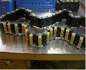
RUBBER ROBOT TRACK
These pictures clearly demonstrate some of the custom
work that we have performed. This gentleman races water
cross. He desired to have anti directional lugs placed in
between his standard lugs. This was an attempt to control
the machine from sliding sideways while racing around the
oval. Another example of how we truly can deliver just
about anything that you want


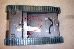
Daryl's Rescue Robot Track
This is the first completed track. You can see the link pins
that will drive the track.

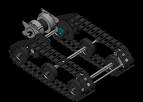
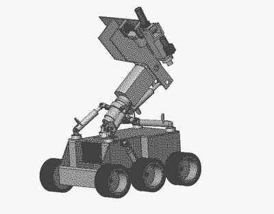
Robot Track Solid Models
This is a picture of the first fully-developed solid model
that I did using SolidWorks. This design used the smaller
batteries from before I realized their limitations. At this
point in time, there are a number of design choices that
I have since changed. You can see here the double-wheel
design, which I threw out when it became apparent how
much the wheel modifications necessary to make this work
would compromise their strength. This design also has a
metal platform, which I have replaced with a transparent
polycarbonate one. Also note no finalized positions for
electronics or computer systems. At this point in time,
I wasn't even planning to have a heat exchanger.

Wednesday, August 23, 2006

Robotic Vacuum

iRobot Roomba is robotic floor cleaner by vacuum It vacuums up
loose particles and applies cleaner to soak up dirt

iRobot® Roomba® Scheduler Vacuuming Robot with Intelli-Bin™


Our new and sleeker looking vacuuming robotic offers you all the
features of Roomba Scheduler, plus the added benefit of Intelli-Bin.
Now enjoy maximum cleaning efficiency as Intelli-Bin tells you
exactly when to empty Roomba's bin. No more guesswork! System
includes filters, brushes, Cleaning Tool and 2 Scheduling Virtual
Walls.

STANDARD FEATURES - Dirt Detect
- Stair Avoidance System
- Surface Transitioning
- Bagless Debris Bin

SPECIFICATIONS Package Dimensions: 21.1”L x 16.9”W x 5.2”H
Package Weight: 11.55 lbs.

www.irobot.com

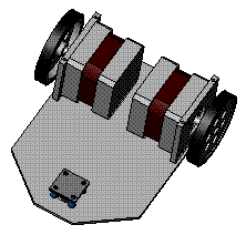
2 wheel robot turns

Robot wheels have very little, if any, sideways motion
(assuming that the center of gravity of the robot is close
to the two wheels). The circle in the front of the robot is
a skid of some soft (this is any smooth piece of plastic,
such as a ping-pong ball or a bottle cap). Because this
skid is smooth, it doesn’t mind making the large sideways
motion, and the robot will turn easily.


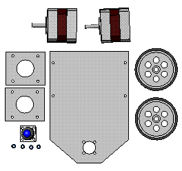
We use two step motor and one ping-pong ball
robot part
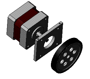
Assembly motor and wheel

Put them to Base plate

Close by top plate


Idea of 4 wheel robot 1

Wheel Robot and Omni wheel Flexiwheel

Monday, August 07, 2006

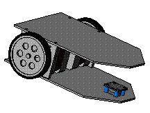
Idea of 2 wheel robot

2 wheel robot is a two-wheeled drive system with independent
actuators for each wheel
it makes it easier to position and control the robot.
This idea we use two step motor for drive robot and two mini wheel
at font and back of robot
Part of robot


Assembly motor and wheel

Put them to Base plate

Close by top plate

Idea of 2 wheel robot 2

Sunday, August 06, 2006

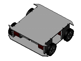
Idea of 4 wheel robot

4 wheel robot can handle relatively rough terrain and move at
high speeds It makes it easier to position and control the robot.
Easy way for make 4 wheel system is used four motor
Part of robot


Assembly motor and wheel

Put them to Base plate
Close by base plate
DC MOTOR and ROBOT WHEEL

Thursday, August 03, 2006

How to control omni-direction wheel

Omni-wheeled system motion
We now consider the motion of a simple omni-wheeled system,
where rotation is fixed. Consider Figure 2.3.1, showing the vectors
acting on one driving wheel.


where, Vw is the velocity of the wheel, θ is the reference wheelangle, Vin is the induced velocity on wheel, φ is the reference body
velocity angle, and Vb is the body velocity of robot.
Now Vin and Vw are always orthogonal:

Vb2 = Vw2 + Vin2 (1)
Also:
Vin2 = Vb2 + Vw2 - 2 Vw Vb cos(θ - φ)
= Vb2 + Vw2 - 2 Vw Vb (cosθ cosφ + sinθ sinφ) (2)
Substituting (2) into (1), we may obtain:
Vw = Vb(cosθ cosφ + sinθ sinφ ) (3)For a given rotational velocity of the centre of mass, w, each
wheel must apply velocity:
Vw= Rw (4)
where R is the distance of the wheel from the centre of mass.
Thus, for each wheel:
Vw = Vb(cosθ cosφ + sinθ sinφ ) + Rw (5)
This is a general equation that is independent of the number
of wheels. Consider a three wheeled omni-directional vehicle
with wheels arranged at angles of 0°, 120° and 240°, equation (5)
yields:
Wheel 1 (θ = 0°): Vw 1 = Vb cosθ +Rw
Wheel 2 (θ = 120°): Vw 2= Vb (-0.5 cosθ+0.866 sinθ)+Rw
Wheel 3 (θ = 240°): Vw 3= Vb (-0.5 cosθ-0.866 sinθ)+Rw

from
Mark Ashmore and Nick Barnes, Omni-drive robot motion on curved
paths: The fastest path between two points is not a straight-line


Omni-wheeled

Friday, June 16, 2006

Basic Robot


WHAT'S called a robot?

Robot should have the ability to think - make decisions.

it has an on-board brain and it can still accept instructions

from an operator and be called a robot


Building Your Robot

Four step for building

  • Design mobility

  • Design Gripper

  • Design Circuit , Senser

  • Programing

...............................................................

Mobility

Type of mobility depends on the job they have to do

and the environment they operate in.

  • - Wheels

  • - Tracks

  • - Legs

.................................................

Wheels

Type of wheel mobility

1. The two wheeled drive

The two wheel drive system is simple

to build because one motor drives one

wheel and another drives the second

wheel. When both motors are going

forward the robot moves forward.

When you reverse one of the motors, the robot turns

2. 4 wheel system is a two wheel drive with two wheel steering

This is a similar system to what is seen on

automobiles thay has a large turning radius

but thay relatively easy to drive

3. 4 wheel system driven

4 wheel system driven by either one or

two motors and the wheels on the other

side are set up in the same fashion the

wheels must skid or slide when the robot is

turning. This means using more battery power and

additional stresses on the drive system and motors

4. omni

The omni wheel is unique because it rolls

freely in two directions. In one direction,

it rolls like a normal wheel. It can also roll

laterally because of the smaller wheels

spread about its circumference. it in any direction. By changing

the speeds and directions of the motors the robot can drive in

any direction without needing to turn. This makes it very useful

for navigating around the house. It works on anyindoor surface

or outdoors in short grass, pavement, concrete, etc

Size of wheels

Wheel size depends on how fast and how heavy.

If your robots move at approximately 15 feet per second.

Of course rams and wedges tend to move faster where as

vicious shell spinners can move slower. To calculate how fast

your robot will move with a specified wheel is simple.

First measure the diameter of the wheel and calculate

the circumference.

Wheel diameter in feet x 3.14 = Circumference

(distance around the wheel)

0.8" x 3.14 = 2.512"


Second, calculate the speed

RPM of the wheel x Circumference = number of feet per minute

230 RPM x 2.512 = 577.76 feet per minute


Forth, convert to feet per second

feet per minute / 60 (seconds in a minute) = feet per second

481.4 / 60 = 8.02 feet per second


The speed here is reasonable if you are building a smaller bot,

such as a feather weight or light weight or even if your building

a heavy weight with a strong weapon. Its a bit on the slow side

for a heavy weight wedge or ram.


How heavy the robot is an important factor in wheel size.

You should try to have about 2 pounds of torque for every

pound of robot. Again, a simple bit of math is required.


Simply divide the torque by the radius

of the wheel (1/2 of the diameter).

480 inch pounds of torque / 4 inch radius = 120 pounds of

torque. The torque is good if your were building light weight.

.....................................................

Tracks
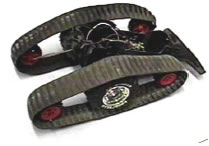
Tracks provide good traction in

loose soil, low ground pressure

and increased surface area.

This increases the capability of

the vehicle to operate in areas

where traction is limited, but leads to inefficiencies on hard

smooth surfaces and may be inadequate in highly cluttered

environments. With tracks attached locomotion is accomplished

via skid steer. Due to the dual drive system, the tracks can be

driven by either of the two motors. Using the walking drive, the

tracks have increased torque, but a lower top speed. Using

the track drive, the tracks have a higher maximum speed, but

lower torque


...................................................................

Legs
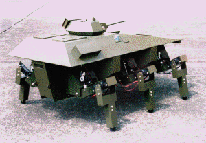
Legs provide better mobility in

highly cluttered environments.

However, legs are less efficient

and more difficult to control

precisely. Legs may also have more difficulty navigating steep

slopes than wheels or tracks. In the legged configuration the

vehicle maneuvers via quadrupedal motion by coordinating the

movements of all four legs simultaneously. Turning is accomplished

by slowing the rate of movement on a side

(similar to skid steer movement). This leads to large turns

(increased turning radius) that may be slow to effect. Stepping

over obstacles can be accomplished by rotating one leg

independently of the others and then continuing with coordinated motion.


.......................................................................


link