INTERFACING AN ANALOG COMPASS TO AN EMBEDDEDCONTROLLER
AbstractThis paper describes the development of a compass sensing unit for use on a remotely operated vessel. The sensor determines the direction of the vessel’s path to aide the user in operating the boat wirelessly through a laptop. The system provides information tofacilitate tracking and controlling the boat when it is not easily seen by the operator. The selected compass, Dinsmore R1655 analog compass sensor, was used in conjunction ofan 8051 microcontroller to provide the necessary data. The system was able to read an analog value from the sensor and convert it to digital direction. The paper will describe the system design and present test results.

http://www.icee.usm.edu/icee/conferences/asee2007/
papers/630_INTERFACING_AN_ANALOG_COMPASS_TO_AN_EMBE.pdf
Microcontroller Design Final Project: Digital Compass
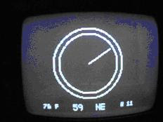
The goal of this project is to build a digital compass that displays both the direction and cardinal points on a television. Other functionalities were added to complement the sensor interface, such as, temperature display, magnetic declination input and disability option.
The goal of this project is to build a digital compass that displays both the direction and cardinal points on a television. Other functionalities were added to complement the sensor interface, such as, temperature display, magnetic declination input and disability option.

http://instruct1.cit.cornell.edu/courses/ee476/FinalProjects/s2004/ccw27/index.htm
Electronic Compass Design using KMZ51 and KMZ52
This paper describes how to realize electronic compass systems using the magnetoresistive sensors KMZ51 and KMZ52 from Philips Semiconductors. Therefore, firstly an introduction to the characteristics of the earth´s magnetic field is given. In the following, the main building blocks of an electronic compass are shown, which are two sensor elements for measuring the x- and y-components of the earth field in the horizontal plane, a signalconditioning unit and a direction determination unit.
Functional block diagram of an electronic compass

http://www.nxp.com/acrobat_download/applicationnotes/AN00022_COMPASS.pdf
Autocalibration of an Electronic Compass for Augmented Reality
Abstract
Electronic compass is often used to provide the absoluteheading reference for tracking the user’s head and handsin Virtual Reality (VR) and Augmented Reality (AR),especially for outdoor AR applications. However,compass is vulnerable to environment magnetismdisturbance. Existing compass calibration methodsrequire complex steps and true heading reference whichis often impossible to be obtained in outdoor ARapplications, and is useful only when compass is inhorizontal plane. An autocalibration method without theneed of heading reference and redundant sensors isproposed in this paper. First the compass error modelbased on physical principle is presented, then thealgorithm to calculate the compensation coefficients witha set of sample measurements of the sensors in thecompass is described. Because the influence of theenvironmental disturbance has been effectivelycompensated, the calibrated compass can providedaccurate heading even when it is under large tilt attitude.
http://csdl2.computer.org/comp/proceedings/ismar/2005/2459/00/24590182.pdf
3-AXIS COMPASS REFERENCE DESIGN with Microcontroller Circuit

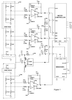
The HMC1052 two-axis magnetic sensor contains two Anisotropic Magneto-Resistive (AMR) sensor elements in a singleMSOP-10 package. Each element is a full wheatstone bridge sensor that varies the resistance of the bridge magnetoresistorsin proportion to the vector magnetic field component on its sensitive axis. The two bridges on the HMC1052 areorientated orthogonal to each other so that a two-dimensional representation of an magnetic field can be measured. Thebridges have a common positive bridge power supply connection (Vb); and with all the bridge ground connections tiedtogether, form the complete two-axis magnetic sensor. Each bridge has about an 1100-ohm load resistance, so eachbridge will draw several milli-amperes of current from typical digital power supplies. The bridge output pins will present adifferential output voltage in proportion to the exposed magnetic field strength and the amount of voltage supply acrossthe bridge. Because the total earth’s magnetic field strengthis very small (~0.6 gauss), each bridge’s vector component ofthe earth’s field will even be smaller and yield only a couple milli-volts with nominal bridge supply values. Aninstrumentation amplifier circuit; to interface with the differential bridge outputs, and to amplify the sensor signal byhundreds of times, will then follow each bridge voltage output.
http://www.ssec.honeywell.com/magnetic/datasheets/hmc1055.pdf
Compass Sensor