 WHAT'S called a robot?
Robot should have the ability to think - make decisions.
it has an on-board brain and it can still accept instructions
from an operator and be called a robot
Building Your Robot
Four step for building
- Design mobility
- Design Gripper
- Design Circuit , Senser
- Programing
...............................................................
Mobility
Type of mobility depends on the job they have to do
and the environment they operate in.
.................................................
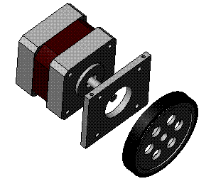
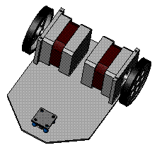
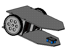
Wheels
Type of wheel mobility
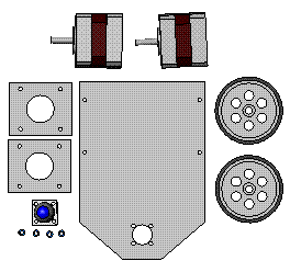
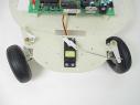
1. The two wheeled drive
 The two wheel drive system is simple
to build because one motor drives one
wheel and another drives the second
wheel. When both motors are going
forward the robot moves forward.
When you reverse one of the motors, the robot turns
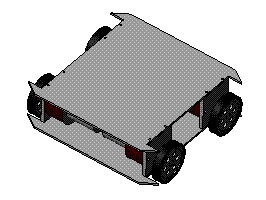
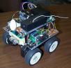
2. 4 wheel system is a two wheel drive with two wheel steering
 This is a similar system to what is seen on
automobiles thay has a large turning radius
but thay relatively easy to drive
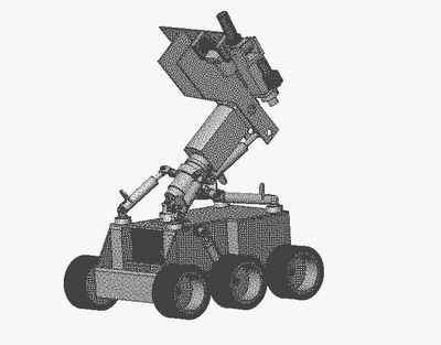
3. 4 wheel system driven
 4 wheel system driven by either one or
two motors and the wheels on the other
side are set up in the same fashion the
wheels must skid or slide when the robot is
turning. This means using more battery power and
additional stresses on the drive system and motors
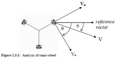
4. omni
 The omni wheel is unique because it rolls
freely in two directions. In one direction,
it rolls like a normal wheel. It can also roll
laterally because of the smaller wheels
spread about its circumference. it in any direction. By changing
the speeds and directions of the motors the robot can drive in
any direction without needing to turn. This makes it very useful
for navigating around the house. It works on anyindoor surface
or outdoors in short grass, pavement, concrete, etc
Size of wheels
Wheel size depends on how fast and how heavy.
If your robots move at approximately 15 feet per second.
Of course rams and wedges tend to move faster where as
vicious shell spinners can move slower. To calculate how fast
your robot will move with a specified wheel is simple.
First measure the diameter of the wheel and calculate
the circumference.
Wheel diameter in feet x 3.14 = Circumference
(distance around the wheel)
0.8" x 3.14 = 2.512"
Second, calculate the speed
RPM of the wheel x Circumference = number of feet per minute
230 RPM x 2.512 = 577.76 feet per minute
Forth, convert to feet per second
feet per minute / 60 (seconds in a minute) = feet per second
481.4 / 60 = 8.02 feet per second
The speed here is reasonable if you are building a smaller bot,
such as a feather weight or light weight or even if your building
a heavy weight with a strong weapon. Its a bit on the slow side
for a heavy weight wedge or ram.
How heavy the robot is an important factor in wheel size.
You should try to have about 2 pounds of torque for every
pound of robot. Again, a simple bit of math is required.
Simply divide the torque by the radius
of the wheel (1/2 of the diameter).
480 inch pounds of torque / 4 inch radius = 120 pounds of
torque. The torque is good if your were building light weight.
.....................................................
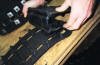
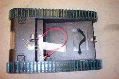
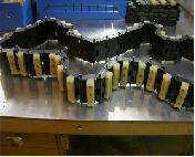
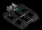
Tracks
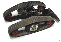
Tracks provide good traction in
loose soil, low ground pressure
and increased surface area.
This increases the capability of
the vehicle to operate in areas
where traction is limited, but leads to inefficiencies on hard
smooth surfaces and may be inadequate in highly cluttered
environments. With tracks attached locomotion is accomplished
via skid steer. Due to the dual drive system, the tracks can be
driven by either of the two motors. Using the walking drive, the
tracks have increased torque, but a lower top speed. Using
the track drive, the tracks have a higher maximum speed, but
lower torque
...................................................................
Legs
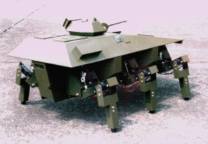
Legs provide better mobility in
highly cluttered environments.
However, legs are less efficient
and more difficult to control
precisely. Legs may also have more difficulty navigating steep
slopes than wheels or tracks. In the legged configuration the
vehicle maneuvers via quadrupedal motion by coordinating the
movements of all four legs simultaneously. Turning is accomplished
by slowing the rate of movement on a side
(similar to skid steer movement). This leads to large turns
(increased turning radius) that may be slow to effect. Stepping
over obstacles can be accomplished by rotating one leg
independently of the others and then continuing with coordinated motion.
.......................................................................
link