Lecture Series on Robotics by Prof.C.Amarnath, Department of Mechanical Engineering,IIT Bombay.
Lecture Robotic Electric Actuators
Lecture Robotic Actuators - Electric, Hydraulic, Pneumatic

Saturday, December 26, 2009
Sunday, December 20, 2009
Lecture Series on Robotics - Industrial,Parallel,Gripper Manipulators and its Kinematics
Lecture Series on Robotics by Prof.C.Amarnath, Department of Mechanical Engineering,IIT Bombay.
Lecture Video Industrial Manipulators and its Kinematics
Lecture Video Parallel Manipulators
Lecture Video Grippers Manipulators
Lecture Video Industrial Manipulators and its Kinematics
Lecture Video Parallel Manipulators
Lecture Video Grippers Manipulators
Thursday, December 17, 2009
Video Lecture Series on Robotics-Technologies in Robots and Industrial Robots
Lecture Series on Robotics by Prof.C.Amarnath, Department of Mechanical Engineering,IIT Bombay. For more details on NPTEL visit http://nptel.iitm.ac.in
Video Lecture Introduction to Robotics
Video Lecture Technologies in Robots
Video Lecture Industrial Robots
Video Lecture Introduction to Robotics
Video Lecture Technologies in Robots
Video Lecture Industrial Robots
Friday, November 27, 2009
Self-assembling Robot
A Self-assembling Lattice Reconfiguration Robot

Telecube modules are cube shaped modules with faces that can extend out doubling the length of any dimension. Each face "telescopes" out, thus the name. Each face also has a latching mechanism to attach or detach from any other face of a neighboring module. We have experimented with shape memory alloy and permanent switching magnet technologies in various versions of this system.
http://www2.parc.com/spl/projects/modrobots/lattice/telecube/index.html
UWE investigates evolving 'swarm' robots
The University of the West of England (UWE) is a partner in 'Symbrion', a ground breaking new European funded project, which will investigate the principles of how large groups (swarms) of robots can evolve and adapt together into different organisms based on bio-inspired approaches.
The aim of the project is to develop the novel principles behind the ways in which robots can evolve and work together in large 'swarms' so that – eventually - these can be applied to real-world applications. The swarms of robots are capable of forming themselves into a 'symbiotic artificial organism' and collectively interacting with the physical world using sensors.

http://info.uwe.ac.uk/news/uwenews/article.asp?item=1231
Self-assembling Robot Video
Robots with a mind of their own Video
Scientists are now building a new kind of robot capable of self-assembly and doing tasks too difficult or too dangerous for human beings.
Self-Replicating Repairing Robots Video
Engineers at Cornell University have designed this odd-looking machine that can rebuild itself and also could perform repairs on itself.
Modular robot reassembles when kicked apart Video
Modular Robot
Wednesday, November 18, 2009
Modular Robot Project
MTRAN
modular robots have been intensively investigated mainly by universities and research institutes in Japan and USA since around 1990 as the robots' versatility, flexibility and fault-tolerance has been attracting researchers' interest.
Experiment of self-reconfiguration by 9 module
As MTRAN is rather smaller and lighter than ever, both self-reconfiguration and dynamical motion of a group is made possible

http://staff.aist.go.jp/e.yoshida/test/research-e.htm
PolyBot
PolyBot is made up of many repeated modules. Each module is virtually a robot in and of itself having a computer, a motor, sensors and the ability to chains PolyBotattach to other modules. In some cases, power is supplied off board and passed from module to module. These modules attach together to form , which can be used like an arm or a leg or a finger depending on the task at hand.
http://www2.parc.com/spl/projects/modrobots/chain/polybot/index.html
PolyBot
Polypod is a bi-unit modular robot. This means that the robot is built up of exactly two types of modules that are repeated many times. This repetition makes manufacturing easier and cheaper. Dynamic reconfigurability allows the robot to be highly versatile, reconfiguring itself to whatever shape best suits the current task. To study this versatility, locomotion was chosen as the class of tasks for examination.
http://www2.parc.com/spl/projects/modrobots/chain/polypod/index.html
Digital Clay
At Xerox PARC it is a subset of the modular robotics project. As such it is a stripped down version of a modular robot. That is, there is a) no active coupling and b) no actuation for producing module to module motions. Changes to an assembly of modules is made by a user. But it embodies one very important aspect—that the modules have some capacity to sense or know their own orientation in space with respect to other modules. As such it may be a useful hardware system for testing software, communications, power distribution for physically modular and reconfigurable systems.
http://www2.parc.com/spl/projects/modrobots/lattice/digitalclay/index.html
Modular Snake Robots
Snake robots can use their many internal degrees of freedom to thread through tightly packed volumes accessing locations that people and machinery otherwise cannot use. Moreover, these highly articulated devices can coordinate their internal degrees of freedom to perform a variety of locomotion capabilities that go beyond the capabilities of conventional wheeled and the recently developed legged robots. The true power of these devices is that they are versatile, achieving behaviors not limited to crawling, climbing, and swimming.
http://www.cs.cmu.edu/~biorobotics/projects/modsnake/modsnake.html
MTRAN3 Modular Robot
Modular robot reassembles when kicked apart
A robot developed by roboticists at the University of Pennsylvania is made of modules that can recognise each other.
Sunday, November 08, 2009
Flying Robot Project
The HoverBot C
An Electrically Powered Flying Robot
SUMMARYThis paper describes the development of a fully autonomous or semi-autonomous
hovering platform, capable of vertical lift-off and landing without a launcher, and capable of
stationary hovering at one location. The idea to build such a model-sized aerial robot is not new; several other research institutes have been working on aerial robots based on commercially available, gasoline powered radio-control model helicopters. However, the aerial robot proposed here, called the HoverBot, has two distinguishing features: The HoverBot uses four rotor heads and four electric motors, making it whisper-quiet, easy-to-deploy, and even suitable for indoor applications. Special applications for the proposed HoverBot are inspection and surveillance tasks in nuclear power plants and waste storage facilities.
Without a skilled human pilot at the controls, the foremost problems in realizing a model helicopter-sized flying robot are stability and control. It is necessary to investigate the stability and control problems, define solutions to overcome these problems, and builde a prototype vehicle to demonstrate the feasibility of the solutions. The proposed HoverBot will have eight input sensors for stability and control, and eight output actuators (4 motors and 4 servos for rotor pitch control). The resulting control system is a very complex, highly non-linear Multiple-Input Multiple-Output (MIMO) system, in which practically all input signals affect all output signals. A surprisingly simple experimental control method, called additive control, is proposed to control the system. This method was successfully used in the current experimental prototype of the HoverBot (although with fewer input signals). It is also proposed to investigate two alternative control methods, adaptive control and neural networks, both of which appear to be especially suitable for the Multiple-Input Multiple-Output control problem.
If successful, the project will result not only in a working prototype of a flying robot, but
it will also provide important insight into the functioning of various control methods for very
complex MIMO systems.
Control of the HoverBot
The control system of the HoverBot is designed to allow either fully autonomous operation or remote operation by an unskilled operator. To either, the HoverBot will appear as an
omnidirectional vehicle with 4 degrees of freedom: (1) up/down (2) sideways, (3) forward/backward, and (4) horizontal rotation.

http://www.cs.cmu.edu/~biorobotics/papers/sbp_papers/integrated1/borenstein_hovercraft.pdf
Creation of a Learning, Flying Robot by Means of Evolution
AbstractWe demonstrate the first instance of a real
on-line robot learning to develop feasible
flying (flapping) behavior, using evolution.
Here we present the experiments and results
of the first use of evolutionary methods for
a flying robot. With nature's own method,
evolution, we address the highly non-linear
fluid dynamics of flying. The flying robot is
constrained in a test bench where timing and
movement of wing flapping is evolved to give
maximal lifting force. The robot is assembled
with standard o®-the-shelf R/C servomotors
as actuators. The implementation is a conventional
steady-state linear evolutionary algorithm.
ROBOT
Five servomotors are used for the robot. They are
arranged in such a way that each of the two wings has
three degrees of freedom. One servo controls the two
wings forward/backward motion. Two servos control
up/down motion and two small servos control the twist
of the wings. The robot can slide vertically on two steel
rods. The wings are made of balsa wood and solar,
which is a thin, light air proof ¯lm used for model
aircrafts, to keep them lightweight. They are as large
as the servos can handle, 900 mm.

http://fy.chalmers.se/~wolff/AWNGecco2002.pdf
Energy-efficient Autonomous Four-rotor Flying Robot
Controlled at 1 kHz
Abstract—We describe an efficient, reliable, and robust fourrotor
flying platform for indoor and outdoor navigation. Currently,
similar platforms are controlled at low frequencies due
to hardware and software limitations. This causes uncertainty
in position control and instable behavior during fast maneuvers.
Our flying platform offers a 1 kHz control frequency and
motor update rate, in combination with powerful brushless
DC motors in a light-weight package. Following a minimalistic
design approach this system is based on a small number of lowcost
components. Its robust performance is achieved by using
simple but reliable highly optimized algorithms. The robot is
small, light, and can carry payloads of up to 350g.

THE FOUR-ROTOR HARDWAREA. General design
Our flying robot has a classical four rotor design with
two counter rotating pairs of propellers arranged in a square
and connected to the cross of the diagonals. The controller
board, including the sensors, is mounted in the middle of the
cross together with the battery. The brushless controllers are
mounted on top of the booms. Figure I shows a photograph
of the flying robot. The weight without battery is 219g. The
flight time depends on the payload and the battery. With
a 3 cell 1800mAh LiPo battery and no payload the flight
time is 30 minutes. We measured the thrust with a fully
charged 3 cell LiPo (12.6V) at 330g per motor. With four
motors the maximum available thrust is 1320g. Since the
controllers need a certain margin to stabilize the robot also
in extreme situations, not all the available thrust can be used
for carrying payload. In addition, efficiency drops and as
a consequence flight time decreases rapidly with a payload
much larger than 350g. Because of this we rate our robot for
a maximum payload of 350g.
With a 350g payload, a flight time of up to twelve minutes
can be achieved. The maximum diameter of the robot without
the propellers is 36.5cm. The propellers have a diameter of
19.8cm each. The sensors used to stabilize the robot are very
small and robust piezo gyros ENC-03R from Murata [14].
The second design iteration of this robot is already functional
but not fully tested and characterized experimentally. This
second version additionally has a three axial accelerometer
and relies on datafusion algorithms, still running at 1kHz,
to obtain absolute angles in pitch and roll.
http://www.societyofrobots.com/robottheory/Energy-Efficient_Autonomous_Four-Rotor_Flying_Robot_Controlled_at_1_Khz.pdf
The ROBUR project: towards an autonomous
flapping-wing animat
Abstract
Flapping-wing flight is not applicable to huge aircrafts, but has a great potential for micro UAVs - as demonstrated by real birds, bats or flying insects. The ROBUR project aims at designing a robotic platform that will serve to better understand the design constraints that this flying mode entails, and to assess its capacity to foster autonomy and adaptation. The article describes the major components of the project, the tools that it will call upon, and its current state of achievement.
Research on flapping flight maneuverability
A generic model of a flapping wing aircraft has been designed, in which lifting surfaces are
modelled by a set of articulated panels (figure 2). In a first stage, this model will be used to
design a simple periodic controller for such a platform by using evolutionary algorithms (figure
3). This controller is expected to generate a periodic, horizontal, flapping flight at a constant
speed.
Physical model used in this project.

http://animatlab.lip6.fr/papers/Doncieux_JMD2004.pdf
Quad-Rotor Flying Robot
New German UAV – microdrone
A high technology very small UAV made in germany by microdrone GmbH. Can reach an altitude of 400m and stay in the sky for 30 minutes
QTAR: Quad Thrust Aerial Robot 2005
Buy Flying Robot
Saturday, August 22, 2009
Snake Robot Project
Anna Konda
The fire fighting snake robotAnna Konda was developed in order to demonstrate the SnakeFighter concept. The robot is to our knowledge the biggest and strongest snake robot in the world and also the first water hydraulic snake robot ever constructed.

Embedded control systemMicrocontrollers (AVR ATmega128) are used to control the motion of the joints of Anna Konda. A communication bus through the robot allows for communication between the microcontrollers and a dedicated controller in the head of the robot (the brain). The brain can communicate with an external computer through a wireless connection based on Bluetooth. This allows the robot to be remotely controlled by an operator.
http://www.sintef.no/Home/Information-and-Communication-Technology-ICT/Applied-Cybernetics/Projects/Our-snake-robots/Anna-Konda--The-fire-fighting-snake-robot/
Robot spy
can survive battlefield damageBentley and his colleague Siavash Haroun Mahdavi borrowed a trick from evolution to allow their robot to adapt to damage. The snakebot is made up of modular vertebral units that "snap" together to form a snake-like body (see graphic). Each unit contains three separate "muscles" running down its length. The muscles are made out of wires of a shape-memory alloy called nitinol, an alloy of nickel and titanium whose crystal structure shrinks when an electric current is applied to it. Usefully, it regains its original shape and length once the current is removed. To make the snakebot move in a particular direction, a current is applied to certain wires. When the current is removed, the wires spring back and the robot will jump forward.


http://www-robot.mes.titech.ac.jp/robot/snake/acm-r5/acm-r5_e.html
The fire fighting snake robotAnna Konda was developed in order to demonstrate the SnakeFighter concept. The robot is to our knowledge the biggest and strongest snake robot in the world and also the first water hydraulic snake robot ever constructed.

Embedded control systemMicrocontrollers (AVR ATmega128) are used to control the motion of the joints of Anna Konda. A communication bus through the robot allows for communication between the microcontrollers and a dedicated controller in the head of the robot (the brain). The brain can communicate with an external computer through a wireless connection based on Bluetooth. This allows the robot to be remotely controlled by an operator.
http://www.sintef.no/Home/Information-and-Communication-Technology-ICT/Applied-Cybernetics/Projects/Our-snake-robots/Anna-Konda--The-fire-fighting-snake-robot/
Robot spy
can survive battlefield damageBentley and his colleague Siavash Haroun Mahdavi borrowed a trick from evolution to allow their robot to adapt to damage. The snakebot is made up of modular vertebral units that "snap" together to form a snake-like body (see graphic). Each unit contains three separate "muscles" running down its length. The muscles are made out of wires of a shape-memory alloy called nitinol, an alloy of nickel and titanium whose crystal structure shrinks when an electric current is applied to it. Usefully, it regains its original shape and length once the current is removed. To make the snakebot move in a particular direction, a current is applied to certain wires. When the current is removed, the wires spring back and the robot will jump forward.

http://www.newscientist.com/article/dn4075
Snakebot
Snakebots that are being developed will be able to independently dig in loose extraterrestrial soil, are smart enough to slither into cracks in a planet's surface, and are capable of planning routes over or around obstacles
Snakebots that are being developed will be able to independently dig in loose extraterrestrial soil, are smart enough to slither into cracks in a planet's surface, and are capable of planning routes over or around obstacles

http://www.nasa.gov/centers/ames/news/releases/2000/00images/snakebot/snakebot.html
Amphibious snake-like robot "ACM-R5"(2005-)
Amphibious snake-like robot "ACM-R5"(2005-)
Sea snakes live in water, and even terrestrial snakes sometimes show swimming on water surface. In fact, the mechanism of snakes’ propulsion is almost same both in water and on ground. An amphibious snake-like robot ACM-R5 (Fig. 1) takes advantage of this fact. It can operate both on ground and in water undulating its long body (Fig. 2, Fig. 3).

The joint of ACM-R5 consists of an universal joint and bellows (Fig 4). It was developed on the basis of the previous model HELIX, which was designed for research of spirochete-like helical swimming. An universal joint plays a role of bones, and bellows do a role of an integument. ACM-R5 can form a smooth shape due to this joint structure, and it is important for effective locomotion. To be precise, the universal joint has one passive twist joint at the intersection point of two bending axis to prevent mechanical interference with bellows.

http://www-robot.mes.titech.ac.jp/robot/snake/acm-r5/acm-r5_e.html
Robot Snake Vedio
Cool Robot Snake
I want one of these! THINK IT'S FAKE? Check out Dr. Gavin Miller's site... http://www.snakerobots.com/... This is the S5 version of S1 thru S7. We HAVE the technology! Some of you younger puppies
Robotic Snake
A robotic snake swimming at the Odensee Robot Festival, August 2007
Slithertron - Robot Snake
Evolution of a Robotic Snake
SuperBot Sidewinder – Amazing
Monday, July 27, 2009
Compass Sensor with Microcontroller Project
INTERFACING AN ANALOG COMPASS TO AN EMBEDDEDCONTROLLER
AbstractThis paper describes the development of a compass sensing unit for use on a remotely operated vessel. The sensor determines the direction of the vessel’s path to aide the user in operating the boat wirelessly through a laptop. The system provides information tofacilitate tracking and controlling the boat when it is not easily seen by the operator. The selected compass, Dinsmore R1655 analog compass sensor, was used in conjunction ofan 8051 microcontroller to provide the necessary data. The system was able to read an analog value from the sensor and convert it to digital direction. The paper will describe the system design and present test results.

http://www.icee.usm.edu/icee/conferences/asee2007/
papers/630_INTERFACING_AN_ANALOG_COMPASS_TO_AN_EMBE.pdf
Microcontroller Design Final Project: Digital Compass
The goal of this project is to build a digital compass that displays both the direction and cardinal points on a television. Other functionalities were added to complement the sensor interface, such as, temperature display, magnetic declination input and disability option.
The goal of this project is to build a digital compass that displays both the direction and cardinal points on a television. Other functionalities were added to complement the sensor interface, such as, temperature display, magnetic declination input and disability option.

http://instruct1.cit.cornell.edu/courses/ee476/FinalProjects/s2004/ccw27/index.htm
Electronic Compass Design using KMZ51 and KMZ52
This paper describes how to realize electronic compass systems using the magnetoresistive sensors KMZ51 and KMZ52 from Philips Semiconductors. Therefore, firstly an introduction to the characteristics of the earth´s magnetic field is given. In the following, the main building blocks of an electronic compass are shown, which are two sensor elements for measuring the x- and y-components of the earth field in the horizontal plane, a signalconditioning unit and a direction determination unit.
Functional block diagram of an electronic compass

http://www.nxp.com/acrobat_download/applicationnotes/AN00022_COMPASS.pdf
Autocalibration of an Electronic Compass for Augmented Reality
Abstract
Electronic compass is often used to provide the absoluteheading reference for tracking the user’s head and handsin Virtual Reality (VR) and Augmented Reality (AR),especially for outdoor AR applications. However,compass is vulnerable to environment magnetismdisturbance. Existing compass calibration methodsrequire complex steps and true heading reference whichis often impossible to be obtained in outdoor ARapplications, and is useful only when compass is inhorizontal plane. An autocalibration method without theneed of heading reference and redundant sensors isproposed in this paper. First the compass error modelbased on physical principle is presented, then thealgorithm to calculate the compensation coefficients witha set of sample measurements of the sensors in thecompass is described. Because the influence of theenvironmental disturbance has been effectivelycompensated, the calibrated compass can providedaccurate heading even when it is under large tilt attitude.
http://csdl2.computer.org/comp/proceedings/ismar/2005/2459/00/24590182.pdf
3-AXIS COMPASS REFERENCE DESIGN with Microcontroller Circuit

The HMC1052 two-axis magnetic sensor contains two Anisotropic Magneto-Resistive (AMR) sensor elements in a singleMSOP-10 package. Each element is a full wheatstone bridge sensor that varies the resistance of the bridge magnetoresistorsin proportion to the vector magnetic field component on its sensitive axis. The two bridges on the HMC1052 areorientated orthogonal to each other so that a two-dimensional representation of an magnetic field can be measured. Thebridges have a common positive bridge power supply connection (Vb); and with all the bridge ground connections tiedtogether, form the complete two-axis magnetic sensor. Each bridge has about an 1100-ohm load resistance, so eachbridge will draw several milli-amperes of current from typical digital power supplies. The bridge output pins will present adifferential output voltage in proportion to the exposed magnetic field strength and the amount of voltage supply acrossthe bridge. Because the total earth’s magnetic field strengthis very small (~0.6 gauss), each bridge’s vector component ofthe earth’s field will even be smaller and yield only a couple milli-volts with nominal bridge supply values. Aninstrumentation amplifier circuit; to interface with the differential bridge outputs, and to amplify the sensor signal byhundreds of times, will then follow each bridge voltage output.
http://www.ssec.honeywell.com/magnetic/datasheets/hmc1055.pdf
Compass Sensor
Sunday, July 05, 2009
Robot Arm Project and Robot ArmVedio
AROBOT ARM TUTORIAL
The robot arm is probably the most mathematically complex robot you could ever build. As such, this tutorial can't tell you everything you need to know. Instead, I will cut to the chase and talk about the bare minimum you need to know to build an effective robot arm.

Design and Application of a 3 DOF Bionic Robot Arm

Robotic arm
Computerized wireless Pick n Place Robot
RoboSim- A Simple 6-DOF Robot Manipulator Simulation System

sbcRobotics


The robot arm is probably the most mathematically complex robot you could ever build. As such, this tutorial can't tell you everything you need to know. Instead, I will cut to the chase and talk about the bare minimum you need to know to build an effective robot arm.

Design and Application of a 3 DOF Bionic Robot Arm
High efforts are put in the mechanical design of industrial manipulators to obtain high position accuracy using rigid joint actuators and rigid arms resulting in heavy masses of arms. For safety reasons, they can only be used in environments strictly separated from humans. Thus they stand in remarkable contrast to animals and humans with their much better relationship from payload to arm weight, and its concurrent high movement quality by "intelligent" control.

Robotic arm
I present the results, hoping it will be useful to other people who are also interested. This robotic arm is a little demonstration, it uses stock servo-motors normally used in RC models, and is controlled from a pc, attached with a serial cable.

Computerized wireless Pick n Place Robot
this is the most advance version of “Pick n Place Robot” perhaps and most popular and widely used in recent industries. A person from a remote place can comfortably control the motion of robotic arm without any wire connection.

RoboSim- A Simple 6-DOF Robot Manipulator Simulation System
RoboSim is a very simple simulation system for a 6 degres of freedom robot manipulator. The basic functions of the control panel are to move the manipulator either in joint coordinates or in cartesian coordinates. It is also possible, to change the view position or change length and color of the links. Joint weights may be set, in order to favor movement of individual joints versus others

sbcRobotics
torsoHead LeftArm stepper motors showing, stepper motor control board, and cardboard hand or fingers. The cardboard fingers are place holders and have been cut to the same proportions as a human hand. This is needed to gauge the real distance for the arm's reach. The fingers will be replaced with the finished hand.

http://www.sbcrobotics.com/sbcRoboticsTorsoHead.htm
Atlas II Robotic SystemATLAS II is a complete robotic system consisting of the robot arm, power supplies, and control microcomputer.
Atlas II Robotic SystemATLAS II is a complete robotic system consisting of the robot arm, power supplies, and control microcomputer.

Robot Arm Made Vedio
Robot Arm on How it's Made
Robotic Arm Made Out of Recycled Materials (Build)
My first Robot Arm
Robotic Arm With Four Degree Of Freedom
articulate robotic arm gripper mechanism
Robot arm with stepper motor
Robot arm simulation in Solidworks2009
Robot Arm on How it's Made
Robotic Arm Made Out of Recycled Materials (Build)
My first Robot Arm
Robotic Arm With Four Degree Of Freedom
articulate robotic arm gripper mechanism
Robot arm with stepper motor
Robot arm simulation in Solidworks2009
Sunday, May 31, 2009
Fish Robot
Fish Robot Project
Principles of the Swimming Fish Robot
We can say that fish swim with pushing water away behind them, though fish swim by various methods. As the well-known categories for the swimming fish, a zoologist, C.M. Breder classified into the following three general categories based on length of a tail fin and strength of its oscillation (see the figure to the right).
(a) Anguilliform: Propulsion by a muscle wave in the body of the animal which progresses from head to tail like the Eel.(b) Carangiform: Oscillating a tail fin and a tail peduncle like the Salmon, Trout, Tuna and Swordfish.(c) Ostraciiform: Oscillating only a tail fin without moving the body like the Boxfish.


http://nereus.mech.ntua.gr/pdf_ps/med03.pdf
A simplified propulsive model of bio-mimetic robot fish
and its realizationSUMMARY
This paper presents a simplified kinematics propulsive model
for carangiform propulsion. The carangiform motion is
modeled as a serial N-joint oscillating mechanism that is
composed of two basic components: the streamlined fish
body represented by a planar spline curve and its lunate
caudal tail by an oscillating foil. The speed of fish’s straight
swimming is adjusted by modulating the joint’s oscillatory
frequency, and its orientation is tuned by different joint’s
deflections. The experimental results showed that the proposed
simplified propulsive model could be a viable candidate
for application in aquatic swimming vehicles.


Principles of the Swimming Fish Robot
We can say that fish swim with pushing water away behind them, though fish swim by various methods. As the well-known categories for the swimming fish, a zoologist, C.M. Breder classified into the following three general categories based on length of a tail fin and strength of its oscillation (see the figure to the right).
(a) Anguilliform: Propulsion by a muscle wave in the body of the animal which progresses from head to tail like the Eel.(b) Carangiform: Oscillating a tail fin and a tail peduncle like the Salmon, Trout, Tuna and Swordfish.(c) Ostraciiform: Oscillating only a tail fin without moving the body like the Boxfish.

http://www.nmri.go.jp/eng/khirata/fish/general/principle/index_e.html
Fish Robot (Analysis And Mathematical Modeling of Thunniform Motion)
This research, Institute of Field Robot (FIBO) use the yellow-fin prototype tuna to build the robot because of its movement ability in high speed for a long time, thunniform mode, which make us believe that its movement will be the most efficient locomotion mode than other aquatic mammals. Additional, the body profile is both symmetrical in horizontal and vertical plane, which is helpful for finding out the equation of motion.

http://fibo.kmutt.ac.th/eng/index.php?option=com_content&task=view&id=265
Model Fish Robot, PPF-06i
It was confirmed that the PPF-06i swims with swimming speed of about 0.1 m/s using the micro-computer. Also, it was confirmed that the PPF-06i turns with turning diameter of about 1 m, when the tail swings to one side during the turning. I think that one of the above purposes, (i) Swimming of the fish robot using R/C servomotors controled by a micro-computer, was achieved approximately.On the other side, another of the purposes, (ii) Simple control by sensors, has not been achieved.

http://www.nmri.go.jp/eng/khirata/fish/model/ppf06i/ppf06ie.htm
Design Concept of the PPF-08iThe model fish robot named PPF-08i has been developed after considering the previous model fish robots, PPF-06i and PPF-07i. The design concept and purposes are as follows:(1) Simple structure(2) Small size(3) High turning performance (small turning diameter),(4) Controlled by a microcomputer,(5) A basic model of the group robots.
Design Concept of the PPF-08iThe model fish robot named PPF-08i has been developed after considering the previous model fish robots, PPF-06i and PPF-07i. The design concept and purposes are as follows:(1) Simple structure(2) Small size(3) High turning performance (small turning diameter),(4) Controlled by a microcomputer,(5) A basic model of the group robots.

http://www.nmri.go.jp/eng/khirata/fish/model/ppf08i/ppf08ie.htm
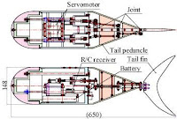
Prototype Fish Robot, PF-600
Prototype Fish Robot, PF-600

The figure to the right shows the structure of the PF-600. A battery, R/C receiver and two servos are located in the body. Two rods connect link mechanisms in the two tail peduncles (forward and tail peduncles), and finally the tail fin through rod seals. For sliding rod seals, slide bearings are used. Other parts that do need to move are sealed with "O" rings.http://www.nmri.go.jp/eng/khirata/fish/experiment/pf600/pf600e.htm
Fish Robot Research
On the Design of an Autonomous Robot FishAbstract—A fish-like propulsion system seems to be an
interesting and efficient alternative to propellers in small
underwater vehicles. This paper presents the early design
stages of a small autonomous robotic vehicle driven by an
oscillating foil. It describes the preliminary dimensioning of
the vehicle and the selection and sizing of the necessary
actuators according to the project’s objectives and constraints.
Finally there is a description of the control system
implementation for the tail’s motion.
Fish swimming is classified as carangiform, anguiliform,
thunninform and ostraciform, depending on the percentage
of their body that contributes in thrust production through
undulatory motions. According to this observation, there
are three alternative ways to design a robot fish, see Fig.

http://nereus.mech.ntua.gr/pdf_ps/med03.pdf
A simplified propulsive model of bio-mimetic robot fish
and its realizationSUMMARY
This paper presents a simplified kinematics propulsive model
for carangiform propulsion. The carangiform motion is
modeled as a serial N-joint oscillating mechanism that is
composed of two basic components: the streamlined fish
body represented by a planar spline curve and its lunate
caudal tail by an oscillating foil. The speed of fish’s straight
swimming is adjusted by modulating the joint’s oscillatory
frequency, and its orientation is tuned by different joint’s
deflections. The experimental results showed that the proposed
simplified propulsive model could be a viable candidate
for application in aquatic swimming vehicles.

Fig. 1. Physical model of fish swimming.http://journals.cambridge.org/download.php?file=%2FROB%2FROB23_01%2FS0263574704000426a.pdf&code=b84242209ac7a0d01e3a1a9fe14560df
Body Construction of Fish Robot in Order
to Gain Optimal Thrust Speed
Abstract
In fish robot, hydrodynamic shape of its body determines
the ability of the robot to swim. However, sometimes the
swimming gait depends not only on the body, but also on
the frequency of tail undulation and body angle when it
attempts to achieve fast swimming. Thrust speed becomes
the main objective in this research. Some variables which
are suspected as important variables influencing the thrust
speed were observed such as body shape, fin, frequency
of tail, and acceleration of tail. Results of investigation
show that there are some significant dependency among
thrust speed, frequency of tail undulation and body shape.
In some conditions it was found that there was some
optimal condition for all parameters which pace the fish
robot towards fastest thrust speed.

-
-
Fish Robot Vedio
Fish robot Vedio
Robot fish – shark vedio
Squid Robot Vedio
Robot fish vedio
AQUAROID ARTIFICIAL ROBOT-FISH VEDIO
Robot fish synchronise into schools vedio
Fish robot Vedio
Robot fish – shark vedio
Squid Robot Vedio
Robot fish vedio
AQUAROID ARTIFICIAL ROBOT-FISH VEDIO
Robot fish synchronise into schools vedio
Fish Robot
Sunday, April 19, 2009
InfraRed Distance Sensor Project
Test Setup for the Sharp GP2D12
Distance Measurement Detector
I use the Sharp GP2D12 non-contact infrared distance sensor
for determining the level of salt on the Water Softener Monitor
project. To test the Sharp sensor and to determine the
voltages at particular distances, I created a test apparatus
out of a level and some machined plastic parts. This test
setup is compatible with the whole family of Sharp distance
sensors, which are capable of different measurement distances
and different types of outputs

more
Design and development of a new sensor
system for assistive powered wheelchairs
Abstract. Many disabled people experience considerable
difficulties when driving a powered wheelchair. Disabled people
who are not able to drive a powered wheelchair are seriously
limited in their mobility. Several robotic assistive wheelchairs
have been devised in the past. These wheelchairs are equipped
with range sensors, which detect obstacles and measure the
distance to the closest object. The authors are involved in this
kind of projects but, although many sensors exist commercially,
they never found satisfactory range sensors for wheelchair
applications. After identifying these sensor requirements, this
paper presents the design of an optical ranging system, more in
particular a lidar (Light Detection and Ranging) scanner for
wheelchair applications. Test results are reported to show that
this scanner meets the identified requirements.

Sensor design
An approach that is now feasible at a modest price
tag, is using a lidar scanner (Light Detection And
Ranging). Various systems already exist on the market
that use light instead of the microwaves of the well
known radar. A lot of research has been done on range
finders, anti-collision systems for the car industry and
pollution surveillance systems. Most of these systems
use large aperture optical telescopes, powerful lasers
and ultra fast electronic devices for the processing of
the data to determinate the time of flight of the emitted
and reflected light. They have a range of several hundred
metres up to a few kilometres. This performance
is much too high and most of these systems are rather
bulky and very expensive and are not always eye-safe.
All these factors exclude their use on a wheelchair.
The range of the obstacle detection system is from zero
up to 4 m. The determination of the time-of-flight in
this range, calls for ultra fast electronics (660 ps time
resolution for a spatial resolution of 10 cm) and puts
a high demand on the switching characteristics of the
opto-electronic components.
In order to keep the complexity of the system, the demand
on the opto-electronic components and the price
tag low, it is proposed to substitute the direct timeof-
flight measurement by the measurement of a phase
shift. The light from an infra-red laser diode is amplitude
modulated with a signal of 5–20 MHz, depending
on intended range or resolution. The difference in
phase between the signals from the transmitted and re-
flected light is directly proportional to the distance. The
advantages of this method are the much lower switch
frequency, the lower data processing speed and the use
of less exotic components. The disadvantages are the
longer time it takes to get the measurement (some microseconds),
compared to the time-of-flight measurement
(some nanoseconds). This is only important in
3D scanning systems where data throughput must be
very high. If the signal-to-noise ratio does not enable
a stable measurement, the bandwidth of the processing
circuit must be further reduced, increasing processing
time. This is not necessarily a drawback in wheelchair
applications because the sample rate can still be suffi-
cient high. Scanning in a horizontal plane can be performed
by a rotating mirror, reflecting transmitted and
received beams, or by rotating optics. The scanning
rate of the lidar amounts to 5 rev/s.
Different modules for the lidar scanner have been
developed:
– aspheric lens design for optical transmitter and
receiver,
– laser diode output stage (transmitter),
– PIN diode preamplifier,
– limiter and phase measurement (distance measuring),
– microprocessor and interface,
– scanning system.
More pdf
Saturday, April 18, 2009
Infrared Distance Sensor with the Microcontroller Project
Infrared and Ultrasonic Scanner
(ATMEGA32 microcontroller)
This project is a short range, infrared and ultrasonic
scanner that uses a standard hobby servo to move the
sensors and a color LCD screen to display the information
from the distance sensors. The information displayed
on the LCD is an overhead view of the scanning area,
with increments of distance from the distance sensors.

Hardware Details:
The core of the project is the ATMEGA32 microcontroller
from Atmel. It controls the servo, gathers information from
the sensors and places the information on the LCD screen.
There is 32K of flash in the microcontroller and the software
uses about 13K of that. Since the LCD uses a maximum of
3.3V, the microcontroller is run at 3.3V.
More
Interfacing the GP2D02 to a Microcontroller PIC and
Sweeping it with a Hobby Servo
The Sharp GP2D02 is a sensitive compact distance measuring
sensor. It required two lines from a microcontroller in order to be
controlled. One line provides the signal to begin a measurement
and also is used to provide a clock signal when transmitting the
distance measure, and the other line is used to transmit the
measurements back to the microcontroller. I interfaced the GP2D02
to a 12CE519 microcontroller rather than my main CPU (16C77) in
order to free up processing time on the 16C77. The GP2D02 requires
an open collector on its input line, so I connected it through a diode
to the 12CE519. The GP2D02 output is connected directly to the
12CE519. As I was limited to one GP2D02 IR sensor per robot,
I used a hobby servo motor to sweep the GP2D02 through a 50
degree pattern in the front of the robot. The servo used was a
Cirrus CS-70 Standard Pro Servo.

more
The MBasic Compiler - DISTANCE SENSORS
TYPES OF DISTANCE MEASURING DEVICES
There are many different types of technologies and devices
used in measuring distance, some of them being: Radar, Sonar,
Laser, Infrared and Ultrasonic. In this chapter Infrared and
Ultrasonic will be covered. Infrared uses light that is invisible to
the human eye. Also Infrared light bounces off almost everything.
Its main disadvantage is that fluorescent lights generate it and that
can cause interference. Ultrasonic uses sound that is inaudible to
the human ear. Its main advantage is that it is not sensitive to objects
of different colors and light reflecting properties. Its disadvantage
is that some materials absorb sound and don’t reflect it.
PROJECT_6
The components used in this project are one Sharp GP2D12
Infrared distance sensors, one Ultrasonic circuit, a buzzer, a rotary
switch circuit (refer to schematic from Project_5) also the parts from
Project_4. Fifteen of the twenty-two I/O pins of the PIC16F876 will
be used in this project.

Distance Sensor
Friday, April 17, 2009
Robot Distance Sensor Device
PING Ultrasonic Distance Sensor
The Parallax PING))) ultrasonic distance sensor provides precise,
non-contact distance measurements from about 3 cm (1.2 inches)
to 3 meters (3.3 yards). It is very easy to connect to BASIC Stamp®
or Javelin Stamp microcontrollers, requiring only one I/O pin.
Features
• Supply Voltage – 5 VDC
• Supply Current – 30 mA typ; 35 mA max
• Range – 3 cm to 3 m (1.2 in to 3.3 yrds)
• Input Trigger – positive TTL pulse, 2 uS min, 5 μs typ.
• Echo Pulse – positive TTL pulse, 115 uS to 18.5 ms
• Echo Hold-off – 750 μs from fall of Trigger pulse
• Burst Frequency – 40 kHz for 200 μs
• Burst Indicator LED shows sensor activity
• Delay before next measurement – 200 μs
• Size – 22 mm H x 46 mm W x 16 mm D (0.84 in x 1.8 in x 0.6 in)
 Ping Datasheet pdf
GP2D12
InfraRed Distance Sensor
DESCRIPTION
The GP2D12 is a distance measuring sensor with
integrated signal processing and analog voltage output.
FEATURES
• Analog output
• Effective Range: 10 to 80 cm
• LED pulse cycle duration: 32 ms
• Typical response time: 39 ms
• Typical start up delay: 44 ms
• Average current consumption: 33 mA
• Detection area diameter @ 80 cm: 6 cm

Distance Sensor
Subscribe to:
Comments (Atom)

