Sunday, April 19, 2009

InfraRed Distance Sensor Project


Test Setup for the Sharp GP2D12
Distance Measurement Detector

I use the Sharp GP2D12 non-contact infrared distance sensor
for determining the level of salt on the Water Softener Monitor
project. To test the Sharp sensor and to determine the
voltages at particular distances, I created a test apparatus
out of a level and some machined plastic parts. This test
setup is compatible with the whole family of Sharp distance
sensors, which are capable of different measurement distances

and different types of outputs

more


Design and development of a new sensor
system for assistive powered wheelchairs


Abstract. Many disabled people experience considerable
difficulties when driving a powered wheelchair. Disabled people
who are not able to drive a powered wheelchair are seriously
limited in their mobility. Several robotic assistive wheelchairs
have been devised in the past. These wheelchairs are equipped
with range sensors, which detect obstacles and measure the
distance to the closest object. The authors are involved in this
kind of projects but, although many sensors exist commercially,
they never found satisfactory range sensors for wheelchair
applications. After identifying these sensor requirements, this
paper presents the design of an optical ranging system, more in
particular a lidar (Light Detection and Ranging) scanner for
wheelchair applications. Test results are reported to show that
this scanner meets the identified requirements.


Sensor design
An approach that is now feasible at a modest price
tag, is using a lidar scanner (Light Detection And
Ranging). Various systems already exist on the market
that use light instead of the microwaves of the well
known radar. A lot of research has been done on range
finders, anti-collision systems for the car industry and
pollution surveillance systems. Most of these systems
use large aperture optical telescopes, powerful lasers
and ultra fast electronic devices for the processing of
the data to determinate the time of flight of the emitted
and reflected light. They have a range of several hundred
metres up to a few kilometres. This performance
is much too high and most of these systems are rather
bulky and very expensive and are not always eye-safe.
All these factors exclude their use on a wheelchair.
The range of the obstacle detection system is from zero
up to 4 m. The determination of the time-of-flight in
this range, calls for ultra fast electronics (660 ps time
resolution for a spatial resolution of 10 cm) and puts
a high demand on the switching characteristics of the
opto-electronic components.
In order to keep the complexity of the system, the demand
on the opto-electronic components and the price
tag low, it is proposed to substitute the direct timeof-
flight measurement by the measurement of a phase
shift. The light from an infra-red laser diode is amplitude
modulated with a signal of 5–20 MHz, depending
on intended range or resolution. The difference in
phase between the signals from the transmitted and re-
flected light is directly proportional to the distance. The
advantages of this method are the much lower switch
frequency, the lower data processing speed and the use
of less exotic components. The disadvantages are the
longer time it takes to get the measurement (some microseconds),
compared to the time-of-flight measurement
(some nanoseconds). This is only important in
3D scanning systems where data throughput must be
very high. If the signal-to-noise ratio does not enable
a stable measurement, the bandwidth of the processing
circuit must be further reduced, increasing processing
time. This is not necessarily a drawback in wheelchair
applications because the sample rate can still be suffi-
cient high. Scanning in a horizontal plane can be performed
by a rotating mirror, reflecting transmitted and
received beams, or by rotating optics. The scanning
rate of the lidar amounts to 5 rev/s.
Different modules for the lidar scanner have been
developed:

– aspheric lens design for optical transmitter and
receiver,
– laser diode output stage (transmitter),
– PIN diode preamplifier,
– limiter and phase measurement (distance measuring),
– microprocessor and interface,
– scanning system.

More pdf

Saturday, April 18, 2009

Infrared Distance Sensor with the Microcontroller Project


Infrared and Ultrasonic Scanner
(ATMEGA32 microcontroller)


This project is a short range, infrared and ultrasonic
scanner that uses a standard hobby servo to move the
sensors and a color LCD screen to display the information
from the distance sensors. The information displayed
on the LCD is an overhead view of the scanning area,
with increments of distance from the distance sensors.


Hardware Details:
The core of the project is the ATMEGA32 microcontroller
from Atmel. It controls the servo, gathers information from
the sensors and places the information on the LCD screen.
There is 32K of flash in the microcontroller and the software
uses about 13K of that. Since the LCD uses a maximum of
3.3V, the microcontroller is run at 3.3V.
More


Interfacing the GP2D02 to a Microcontroller PIC and
Sweeping it with a Hobby Servo


The Sharp GP2D02 is a sensitive compact distance measuring
sensor. It required two lines from a microcontroller in order to be
controlled. One line provides the signal to begin a measurement
and also is used to provide a clock signal when transmitting the
distance measure, and the other line is used to transmit the
measurements back to the microcontroller. I interfaced the GP2D02
to a 12CE519 microcontroller rather than my main CPU (16C77) in
order to free up processing time on the 16C77. The GP2D02 requires
an open collector on its input line, so I connected it through a diode
to the 12CE519. The GP2D02 output is connected directly to the
12CE519. As I was limited to one GP2D02 IR sensor per robot,
I used a hobby servo motor to sweep the GP2D02 through a 50
degree pattern in the front of the robot. The servo used was a
Cirrus CS-70 Standard Pro Servo.


more


The MBasic Compiler - DISTANCE SENSORS
TYPES OF DISTANCE MEASURING DEVICES


There are many different types of technologies and devices
used in measuring distance, some of them being: Radar, Sonar,
Laser, Infrared and Ultrasonic. In this chapter Infrared and
Ultrasonic will be covered. Infrared uses light that is invisible to
the human eye. Also Infrared light bounces off almost everything.
Its main disadvantage is that fluorescent lights generate it and that
can cause interference. Ultrasonic uses sound that is inaudible to
the human ear. Its main advantage is that it is not sensitive to objects
of different colors and light reflecting properties. Its disadvantage
is that some materials absorb sound and don’t reflect it.


PROJECT_6
The components used in this project are one Sharp GP2D12
Infrared distance sensors, one Ultrasonic circuit, a buzzer, a rotary
switch circuit (refer to schematic from Project_5) also the parts from
Project_4. Fifteen of the twenty-two I/O pins of the PIC16F876 will
be used in this project.

Distance Sensor

Friday, April 17, 2009

Robot Distance Sensor Device


PING Ultrasonic Distance Sensor

The Parallax PING))) ultrasonic distance sensor provides precise,
non-contact distance measurements from about 3 cm (1.2 inches)
to 3 meters (3.3 yards). It is very easy to connect to BASIC Stamp®
or Javelin Stamp microcontrollers, requiring only one I/O pin.
Features
• Supply Voltage – 5 VDC
• Supply Current – 30 mA typ; 35 mA max
• Range – 3 cm to 3 m (1.2 in to 3.3 yrds)
• Input Trigger – positive TTL pulse, 2 uS min, 5 μs typ.
• Echo Pulse – positive TTL pulse, 115 uS to 18.5 ms
• Echo Hold-off – 750 μs from fall of Trigger pulse
• Burst Frequency – 40 kHz for 200 μs
• Burst Indicator LED shows sensor activity
• Delay before next measurement – 200 μs
• Size – 22 mm H x 46 mm W x 16 mm D (0.84 in x 1.8 in x 0.6 in)


Ping Datasheet pdf


GP2D12
InfraRed Distance Sensor

DESCRIPTION
The GP2D12 is a distance measuring sensor with
integrated signal processing and analog voltage output.
FEATURES
• Analog output
• Effective Range: 10 to 80 cm
• LED pulse cycle duration: 32 ms
• Typical response time: 39 ms
• Typical start up delay: 44 ms
• Average current consumption: 33 mA
• Detection area diameter @ 80 cm: 6 cm


Distance Sensor

Thursday, April 16, 2009

Ultrasonic Distance Sensor with the Microcontroller Project


Accurate Ultrasonic Distance Measurement Project

Abstract - This paper introduces a different approach to
the measurement of the time-of-flight of ultrasonic signals.
Frequency variation monitoring and recording is used to
determine accurately the arrival time of the ultrasonic signal.
A high speed Digital Signal Processor (D.S.P.) is used for
both: transmission and direct measurement of the frequency
of the incoming signal in every single period and with an
accuracy of about 0.1%. The proposed configuration offers
small size and low cost solution to displacement
measurements with a remarkable performance in terms of
accuracy, range and measurement time.

THE SYSTEM
The configuration of the proposed system is based on the
capabilities of accurate time measurement of modern microcontrollers.
The usual series of microcontrollers can not be
used in this application mainly because of their relatively
low frequency of operation (clock frequency) which affects
the accuracy of time measurement within one single period.
They can not offer the required fast and accurate frequency
measurement. A high performance system may therefore be
built only on a more powerful microcontroller. Larger
systems (personal computer type, etc) are avoided for
practical reasons; the overall measurement system should be
cost-effective and small sized.


More pdf


Ultrasonic Distance Sensor Implemented
with the Microcontroller Project

Linear measurement is a problem that a lot of
applications in the industrial and consumer market
segment have to contend with. Ultrasonic technology is
one of the solutions used by the industry. However, an
optimized balance between cost and features are a must
for almost all target applications. The ultrasonic distance
measurer (UDM) is used mainly when a non-contact
measurer is required. This is the type of solution this
document explains using a simple robot toy
implementation.

Description
The UDM is a demo that shows capability and performance
of the MC9RS08KA2 and the ultrasonic sensor to build a
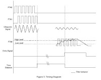
distance measurer. Figure 2 shows the basic building block of
this project.


The firmware generates a 40 kHz burst signal. After the 10 cycle
burst is completed, a variable that measures the distance is
activated. This variable measures the time sound takes to rebound
and is used for distance calculation.

The burst signal goes to the ultrasonic transmitter (US Tx) and is
transmitted as ultrasound through the air Figure 2. When the wave
is reflected off an object, this wave is captured by the ultrasonic
receiver (US Rx.) This received signal is amplified because it
attenuates as it travels. Afterwards, the signal goes back to the
microcontroller unit (MCU), filters it and calculates the distance.
A 40 kHz interrupt is generated by the timer in the MCU. To
perform this, the keyboard interrupt (KBI) is enabled and detects
the external signal. Every time the MCU is interrupted the counter
is increased by three. And the variable used as a counter is
decreased by one for the entrances to the modulus timer module
(MTIM) interrupt service routine (ISR). When this variable is bigger
than eight the ECHO signal is activated. The distance variable is then
set to 0. Refer to Figure 3 for timing diagram. For detailed information
about the firmware see Figure 3.


Distance Sensor

Sunday, April 12, 2009

Two-wheel balancing robot Video

Two-wheel balancing robot built with fischertechnik


balancebot


Remotely Operated Balancing Robot


nBot balancig robot


Self-balancing Robots

Saturday, April 11, 2009

Two-Wheeled Balancing Robot Project 3


nBot Balancing Robot
The basic idea for a two-wheeled dynamically balancing
robot is pretty simple: drive the wheels in the direction
that the upper part of the robot is falling. If the wheels can
be driven in such a way as to stay under the robot's
center of gravity, the robot remains balanced. In practice
this requires two feedback sensors: a tilt or angle sensor
to measure the tilt of the robot with respect to gravity,
and wheel encoders to measure the position of the base
of the robot. Four terms are sufficient to define the motion
and position of this "inverted pendulum" and thereby
balance the robot. These are 1) the tilt angle and 2) its
first derivative, the angle velocity, and 3) the platform
position and 4) its first derivative, the platform velocity.
These four measurements are summed and fed back to
the platform as a motor voltage, which is proportional to
torque, to balance and drive the robot. Here is a diagram

of the algoithm with some code and implementation notes.

more


Gyrobot - a balancing robotic platform


To balance a platform one needs to know the forces acting
upon it. The force is related to the angle of tilt. The base
counteracts that force by applying torque to the wheels.
Basically, one multiplies the angle of tilt by a factor and
uses that to drive the wheels. With appropriate factors the
base will balance, sort of.
more


UBC Self Balancing Robot
The UBC Two-Wheeled Robot (TW Robot) is a device
capable of balancing itself on two wheels only. This Robot
is specifically designed for a controls course, enabling
students to implement custom controller algorithm in real
world applications. The TW Robot was designed and
constructed as a senior Mechatronics design project in
a team of four: Ramin Sahebjavaher, Daria Aminshahidi,
Mohammadreza Izadpanah and Sunil Kumar Gulabani.
The project was supervised by Dr. Xiaodong Lu.
The budget was set at 2500 CAN$.


more


T.O.B.B.
T.O.B.B. has no wheel encoders yet. The controll loop is
a simple P-loop. The mechanical system shows a strong
lowpass behaviour (the batteries are on top yielding a high
rotational inertial moment). That's probably why it works.
The next thing is to improve the drive mechanism. There is
a lot of play in the gears (nBot style motor configuration).
The next version will have belts which should work better
(My mechanical skills are close to 0. Building something
with enough precision needed to match two gears is
probably beyond my capabilities

Two-Wheeled Balancing Robot Project 2

Tip two wheeled balancing robot
The first step in building Tip was to create a simulation.
I used Delphi, a Visual Object Pascal tool, to write a
simulation program. The robot is modeled as a system
composed of two masses. A wheel and platform mass
and a body mass located at a specified distance above
the wheel center. The simulation assumes that the
robot wheels do not slip. The moment of inertia is
calculated for the body mass and the wheel mass is
considered to be a translating mass only with no
consideration for wheel/motor rotational inertia.

more

Two Wheeled Balancing Transport PlatformA senior design team at Rensselaer Polytechnic Institute
(RPI) set out to develop an interdisciplinary mechatronic
system by designing and prototyping a two-wheeled robotic
locomotion platform inspired by (and with the permission of)
the Segway Corporation, maker of the Segway Human
Transporter. The Two-Wheeled Balancing Transport
Platform utilizes parallel-wheel locomotion to provide precise
maneuverability while maintaining system stability. The team
tackled both the complexity involved in modeling, analyzing,
and controlling the platform, as well as the implementation
of two fully-operational prototypes in a four-month time period.
more

Building Bender, the Balancing Bot
Editor's note:
Ted Larson and Bob Allen are members of
the
HomeBrew Robotics Club. They're also the brains
behind Bender, a self-balancing robot that won the Open
class gold medal at this year's ROBOlympics. On tonight's
episode of "The Screen Savers," Larson and Allen will
show off Bender and tell you how they built the
gyro-balanced robot. Below, Allen gives a preview.


more

Low Cost Gyro-Accelerometer Combo SensorProject Summary
In building a balancing robot you need a gyroscope unit and
an accelerometer unit in order to get it to balance. But I also
wanted it to be reasonably low in cost with high performance
and easily interfaced to a MCU. Some of the other solutions
are prohibitively expensive, even if they may work well. Also
the solution I had in mind had to be fairly small and use up
little space and use up little power too. So when Analog
Devices recently came out with their ADXRS150 and
ADXRS300 piezo-gyroscope integrated circuit, I now had a
solution that had low cost and low power with high
performance too. The gyro is very small at about 5mm
square (about 0.3 inches square). You can see the small
combo gyro PCB mounted vertically in the center section
on the balancing robot photo below.


more
 

Friday, April 10, 2009

Two-Wheeled Balancing Robot Project 1

Balancing a Two-Wheeled Autonomous Robot
This thesis discusses the processes developed and
considerations involved in balancing a two-wheeled
autonomous robot based on the inverted pendulum
model. The work was conducted in collaboration with
the Centre for Intelligent Information Processing
Systems (CIIPS) and the School of Mechanical
Engineering.


more pdf

Building a Balancing Robot with the IntelliBrain™
Robotics Controller and Lego® BricksThe balancing robot shown above is a highly unstable two
wheeled robot. The largest mass, the battery pack, is
positioned above the axle, making the robot an
inverted pendulum. The robot will naturally tend to tip over,
and, the further it tips, the stronger the force causing it to tip


more pdf

Self-Balancing Robot
Abstract
This project will undertake the construction and implementation
of a two-wheeled robot that is capable of balancing itself. The
structural, mechanical, and electronic components of the bot
will be assembled in a manner that produces an inherently
unstable platform that is highly susceptible to tipping in one axis.
The wheels of the robot are capable of independent rotation in
two directions, each driven by a servo motor. Information about
the angle of the device relative to the ground (i.e. tilt) will be
obtained from sensors on the device. The precise type of sensor
that will be used is yet to be specified. The tilt sensor may be
an accelerometer, gyroscopic sensor, or IR sensor (to measure
distance to the ground). Information from the sensors will be fed
back to the Z8, which will process the feedback using a crude
proportional, integral, derivative (PID) algorithm to generate
compensating position control signals to the servo motors in
order to balance the device.


more pdf


The Embodiment Design of a Two-Wheeled
Self-Balancing Robot

Abstract.
The embodiment design of a two-wheeled selfbalancing
human augmentation robot for the mobility-challenged
is reported. The prototype relies on a dead-reckoning multisensor
system consisting of i) two optical incremental encoders
and ii) a solid-state tilt sensor. The command inputs are provided
to the robot controller, which is based on PC/104 technology, by
means of a RF control unit. After describing the research motivation
and application of the system, a set of robot design solutions
is outlined along with technical discussions on component layout,
payload holder and chassis design issues. A few simulation results
on the motion control performance are included as well

Wednesday, April 08, 2009

light Finder Robot Project

light finder robotBuilding an autonomous light finder robot
The design of our new robot is very different. It is cheap and you
will be able to build it from parts that are available almost
everywhere around the world. It is an autonomous robot
controlled by an AVR microcontroller. As an autonomous robot
(not controlled by a person) we programmed it to run towards
the brightest spot in the room.


more


Light Finder RobotIn this picture you can see the front of the robot with the light
sensitive resistors and my custom made touch sensor. The
touch sensor basically works by having the basic atom pro
reading the voltage on that line, if the front part is pressed it
closes the circuit and so pulls the voltage high. There is a
resistor there as well on the actual circuit part to prevent short
circuiting. Again we see obligatory judicious usage of gorrilla
duct tape, which is essential for any project.


more


Making an Amplified Color Sensor from an LED and an Op AmpPhotodiode Amplification
Unfortunately, even under the best conditions, photodiodes
(and reversed LEDs) don't provide a lot of current flow. The
output of the photodiode needs to be amplified for the
light-detection signal to be useful in most circuits. A photodiode
amplified by a built-in transistor is called a phototransistor.
You can connect a standalone photodiode to the input of a
standalone transistor. But, it isn't easy to control the gain of a
single-transistor amplifier, and there are issues with signal
noise and the amount of input current required. Instead, a
better method for amplifying low-power signals in a high-quality
repeatable way is an op amp chip (operational amplifier).


more


LIGHT CHASER - A Modified MOVIT Robot
This is the project of a Light Chaser robot. The robot will turn
towards the brightest light and move forward chasing or
following it. It has two motors (left & right) in order to make the
turns; on top two light sensors (photodiodes) separated by a
PC board in order to simulate "a nose". This nose is
particularly important because it will provide a shadow thus
preventing both sensors from being illuminated when a side
light is present (the motor on the non-illuminated sensor
side will turn on thus aiming the robot towards the light).
When the light is right in front of the sensors, there will be
no shadow and both sensors will be equally illuminated, i.e.:
both motors will be running and the robot will move forward.

Photodiode

Tuesday, April 07, 2009

Line Tracking Robot Video

Line Tracking Robot


Line tracking robot by csmig(CASE)


Line tracking Robot - the success story


Line Tracking Robot Microcomputer Assignment


MABL - Maze Navigation Using Line Tracking Sensors at RIT


Az-mOoJoY-N'EARN line tracking Robot


Line Tracking Robot

Sunday, April 05, 2009

Line Tracking Robot Project

Two Inexpensive Line Tracking Sensors for the MIT
Handy Board Microcontroller
1.Theory of OperationA line sensor in its simplest form is a sensor capable of detecting
a contrast between adjacent surfaces, such as difference in color
, roughness, or magnetic properties, for example. The simplest
would be detecting a difference in color, for example black and
white surfaces. Using simple optoelectronics, such as infrared
photo-transistors, color contrast can easily be detected . Infrared
emitter/detectors or photo-transistors are inexpensive (usually
under $1 per sensor) and are easy to interface to a microcontroller.
In addition, standard red LEDs and Cds photocells work well too
and fall in the same price range as the infrared photo-transistors.


2. Construction
3. Sample Code
Sample Interactive C Code for the Handy
Board Microcontroller4. Final Design of the Sensor and Robot
5. Performance

more


Line Tracking Robot ProjectThis project is based on the MOVIT/OWIKIT LINE TRACKER
kit. Each group of three students is provided with one kit.
However, to make the project more meaningful, each group
will construct and test each of the electrical subsystems of the
robot on a breadboard and test it. After the entire system is
put together in this fashion and its operation understood, each
group will also put the pre-wired kit together and observe its
behavior.


more


Line Follower ROBOT
I designed my Robot, which use two motors control rear wheels
and the single front wheel is free. It has 4-infrared sensors on
the bottom for detect black tracking tape, when the sensors
detected black color, output of comparator, LM324 is low logic
and the other the output is high.


SoftwareSoftware for write to AT89C2051 is robot1.hex ,which was
written by C-language ,the source code is robot1.ccompiled
by using MC51 in TINY model with my start up code
robot.asm .
more

Sandwich, an Easy to Build Robot That Follows Lines


I've built four Sandwich robots so far. Three of them are pictured
above (Sandwich, Blue Sandwich, and Red Sandwich) and one
robot was given away (Green Sandwich). The robots are named
for the color of the m&m's mini mega candy tube that connects
their motors together.

Line Tracking Robot

Friday, April 03, 2009

Robot Line Tracking Sensors Circuit

The infrared emitter and detector sensors
Figure 4. Circuit diagram for the infrared emitter/detector line
sensor for the MIT Handy Board. If you plan on making the
sensor from color LEDs and Cds photocells, replace the IR
emitter with a red LED and the IR detector with a Cds photocell.
Click here for a circuit diagram if the sensor is used with other
microcontrollers. Note the subtle difference in the way the IR
detector is configured for this design.


more

Building the sensor
Here is the electronic circuit of the LDR based line sensor we
used in our robots in the Robocon 2007 competition. As you
can see it is composed of eight cells, each one resembling the
cell in figure 3.B. There are many reasons to choose to build
a sensor with exactly eight cells, no more, no less: Eight can
provide enough precision, it connects directly to one port of
the microcontroller, and is represented by one single Byte of
data, making it easier to implement in the programming and
in the memory of an 8 bit microcontroller.


more


Photo Interrupters
The LED emits infrared radiation. If the Photo Interrupter passes
over a white surface, the infrared light is reflected back and is
detected by the phototransistor. Let us assume that this is the
case for the right (shown in red) photo interrupter assembly. The
result is that the emitter-collector resistance drops and a large
current flows through the red 27k resistor. This created a large
voltage drop across this resistor and VR is reduced to near zero.
If at the same time, the left photo interrupter assembly (shown
in blue) is over the black line, the radiation is not reflected back
to the phototransistor and the emitter-collector resistance
remains high. This results in a small current through the blue 27k
resistor. The resulting small voltage drop across this resistor
leads to a high value of ~9 V for VL. We send these two voltages
to a comparator, which then makes one of the two wheels of the
robot rotate in such a fashion that it turns to the left.


Photodiode and Robot Line Tracking

Thursday, April 02, 2009

Digital Light Sensor to MICROCONTROLLER Circuit


ISL29001


The ISL29001 is an integrated ambient light sensor with
ADC and I2C interface. With a spectral sensitivity curve
matched to that of the human eye, the ISL29001 provides
15-bit effective resolution while rejecting 50Hz and 60Hz
flicker caused by artificial light sources.
In normal operation, the ISL29001 consumes less than
300µA of supply current. A software power-down mode
controlled via the I2C interface disables all but the I2C
interface. A power-down pin is also provided, which reduces
power consumption to less than 1µA.
The ISL29001 includes an internal oscillator, which provides
100ms automatic integration periods, or can be externally
timed by I2C commands. Both the internal timing and the
illuminance resolution can be adjusted with an external
resistor.

ISL29001 datasheet pdf


Microcontroller Advanced Kit - Light Sensor Project

This tutorial shows how to set up a microcontroller based
system that converts a signal from a light sensor to a 6 bit
digital value. This value can be used by the microcontroller,
perhaps for a robotic controller, or as in this tutorial, sent to
the PC. It uses the AT89C2051 microcontroller to collect
data and send it to the PC. A MAX232CPE chip is used to
convert the signals from and to RS232 levels for sending
and receiving through the serial port. The 2051 microcontroller
has a built in analog comparator that is used to make a
simple analog to digital converter to convert the light sensor
output to a digital value.


Wednesday, April 01, 2009

Light Sensor Circuit 2


Light-controlled pond pump
This circuit was constructed to control the pump in a garden
pond, so that it automatically turns on at dawn and off again
at dusk. Not only does this mean that we don’t have to get
cold and wet when turning the pump on or off manually but
it’s also one less job for our kind neighbours when we go
away on holidays!


more

Light Detection Using A Phototransistor and Voltage
Comparator
This page describes an example project that turns on a red
LED when light is dim and a green LED when light is bright.
Or more to the point, changes color when objects (such as
a fan blade) pass in front of it.Because the lighting required

to enable either LED is controlled by individual potentiometers,

they can be set such that either, neither, or both LEDs turn on.

That is, the red LED doesn't have to turn on simply because the

green LED turned off.


more

Internals of RCX Input Ports and Sensors
When it comes to the active sensors these are much more
complicated inside as can be seen from the figures 4 to 7.
There is however still a simple relationship between the raw
value measured and the sensor resistance if the A/D
conversion takes place with no power is supplied to the


more


Laser Pointer Triggered On/Off Switch
Remote control is commonly performed with either modulated
infrared emitters or radio-frequency wireless transmitters.
During a boring presentation, it occurred to me that the
presenter could control a slide show by aiming their laser
pointer at a list of commands with bullet-point targets.
Alternatively, someone lying in bed could set the clock
alarm/snooze (across the room) or turn off lights by simply
aiming the laser dot at the correct spot on the desired object.